Update Required
To play the media you will need to either update your browser to a recent version or update your
Flash plugin.
Update Required
To play the media you will need to either update your browser to a recent version or update your
Flash plugin.
The processing has been done with the SPW software developed by Parallel Geoscience.
The processing sequence of each shot includes: amplitude recovery, deconvolution in the 15 - 150 Hz frequency bandwidth, tail mute, static corrections.
The deconvolution is done to increase the resolution and attenuate the surface waves. A tail mute is used to kill the air waves and the surface waves.
The static corrections are done to compensate the effects of the weathering zone. In the example, the 3D static corrections are very weak.
The data are sorted in Common Mid-Point gathers (CMP) and compensated for the obliquity effect of the ray paths, due to the offset variation between source and receiver.
These corrections, called Normal Move Out (NMO) corrections are done with a stacking velocity model obtained by velocity analysis.
Surface consistent residual statics are computed to enhance the signal to noise ratio and preserve the high resolution of the data in the CMP stack procedure.
-
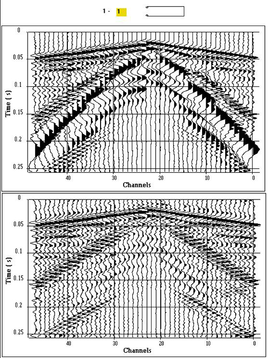
Step 1: Example of a near Offset 3D shot point before and after deconvolution.
The shot point is the shot number 1 situated on the line 1.
-
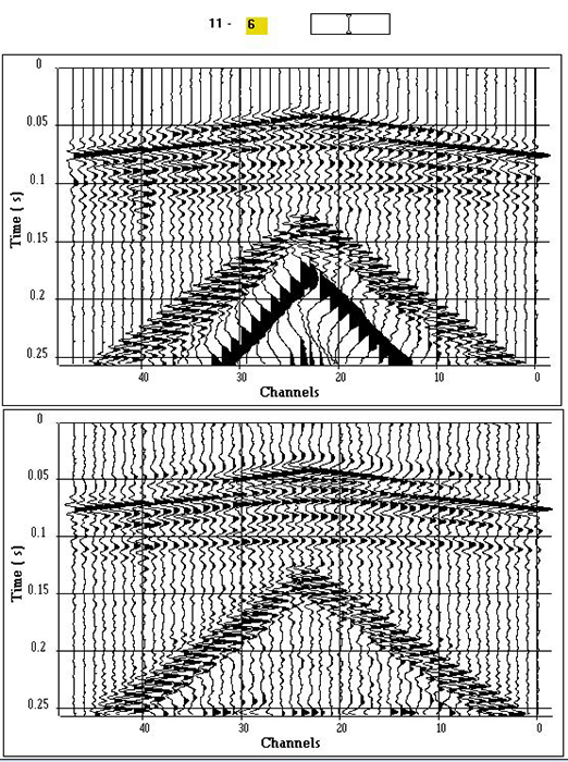
Step 2: Example of a far Offset 3D shot point before and after deconvolution.
The shot point is the shot number 6 situated on the line 11. One can clearly see a reflected event at 100 ms, after deconvolution.
-
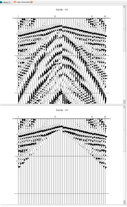
Step 3: Example of a raw shot before and after tail mute.
A tail mute is used to kill the air waves and the surface waves. For each seismic trace, the samples recorded after the specified tail mute time are set equal to zero.
The tail mute time is the offset to velocity ratio. The offset is the source receiver distance and the velocity is 400 m/s.
-
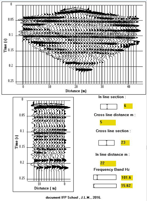
Step 4: CMP stacked sections.
The 3D block is composed of 13 in-line sections 1 m apart. Each section is composed of 44 CMP points 1 m apart.
Figure shows an example of in-line and cross-line seismic sections extracted from the 3D block. The two sections presented (section 6 in the in-line direction,
and section 23 in the cross-line direction) intersect in the middle of the 3D block. They have been filtered in the 15-150 Hz bandwidth, which provides an excellent
signal-to-noise ratio. The CMP point located at the intersection of the in-line seismic section No. 3 and cross-line No. 6 is located about twenty meters from a borehole
in which a vertical seismic profile (VSP) has been recorded.


