Update Required
To play the media you will need to either update your browser to a recent version or update your
Flash plugin.
Update Required
To play the media you will need to either update your browser to a recent version or update your
Flash plugin.
The transmission of an acoustic wave through geological formations is used for formation characterisation. Monopole-type tools are the most commonly used. Sources and receivers are multidirectional.
-
Step 1: Acoustic tool
The tool use for the acquisition of acoustic data is a flexible monopole tool with two far offset receivers R1 and R2. The offset between the source and the receiver R1
is 3 meters. The distance between the two receivers is 25 centimeters. The sampling interval in time is 5 microseconds and the recording time is 5 milliseconds.
The sampling interval in depth is 2 centimeters.
-
Step 2: 3 meters constant offset section
Full waveform acoustic measurements are represented as constant-offset sections. A constant-offset section is a set of acoustic recordings represented as a function
of depth, obtained with a fixed source-to-receiver distance. Figure shows a 3 m constant offset section (R1)
The acoustic section shows:
- Synchronization signals in the time interval 0 - 0.5 ms. These electronic signals have no geological meaning.
- Resonances in the time interval 0.6 - 0.8 ms, locally in depth. The resonance phenomena are linked to bad cementing of the casing to the formation. In the depth
range 75 - 90 m, the resonances interfere with the acoustic signals propagating in the formation.
- Formation refracted waves. The first arrival times of these waves vary from 1.8 ms to 0.7 ms in the depth range 30 m to 80 m. This change in arrival time indicates
a gradual increase in formation velocity with depth. There is also a change in the character of the acoustic signal: low frequency in the range 30-65 m, high frequency
and noise for depths greater than 65 m.
- Stoneley waves. These high-amplitude waves appear after 2.4 ms. They are influenced by casing.
-
Step 3: Cementing index
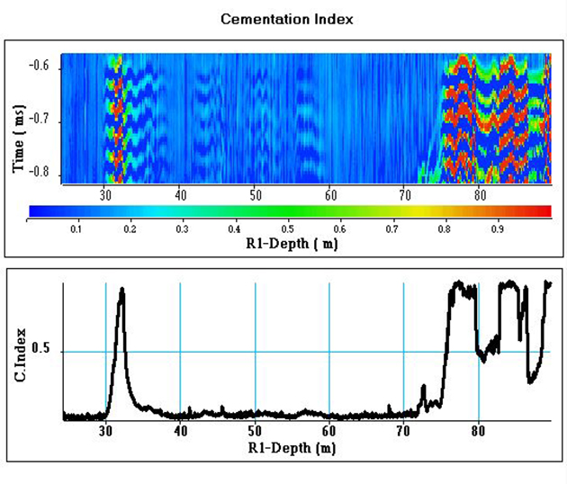
Figure shows the acoustic section in the time interval 0.6-0.8 ms where the resonances are mainly observed. The resonance level can be estimated by calculating,
over the time interval, the energy of the acoustic signal. The normalized energy of the acoustic signal as a function of depth is an acoustic log which is used
to provide a log of the quality of cementing, here called C. index (cement index). The cementing index indicates areas of poor cementing, especially in
the range 30-35 m and at depths greater than 75 m.


